| PREVIOUS | INDEX | NEXT |
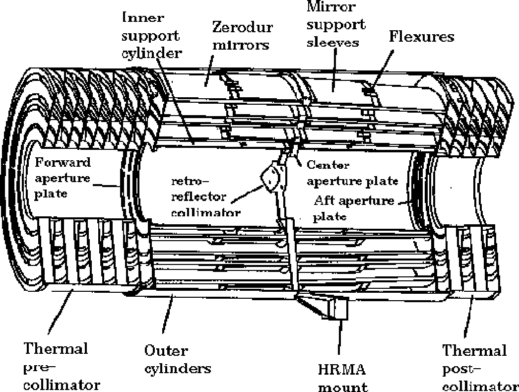
| Optics | Wolter Type-I | |||||||||
| Mirror coating | Iridium (330 Å, nominal) | |||||||||
| Mirror outer diameters (1, 3, 4, 6) | 1.23, 0.99, 0.87, 0.65 m | |||||||||
| Mirror lengths (Pn or Hn) | 84 cm | |||||||||
| Total length (pre- to post-collimator) | 276 cm | |||||||||
| Unobscured clear aperture | 1145 cm2 | |||||||||
| Mass | 1484 kg | |||||||||
| Focal length | 10.070 ±0.003 m | |||||||||
| Plate scale | 48.82 ±0.02 μm arcsec−1 | |||||||||
| Exit cone angles from each hyperboloid: | ||||||||||
| θc (1, 3, 4, 6) | 3.42°, 2.75°, 2.42°, 1.80° | |||||||||
| θd (1, 3, 4, 6) | 3.50°, 2.82°, 2.49°, 1.90° | |||||||||
| f-ratios (1, 3, 4, 6) | 8.4, 10.4, 11.8, 15.7 | |||||||||
| PSF FWHM (with detector) | < 0.5 arcsec | |||||||||
|
| |||||||||
| Ghost-free field of view | 30 arcmin diameter |
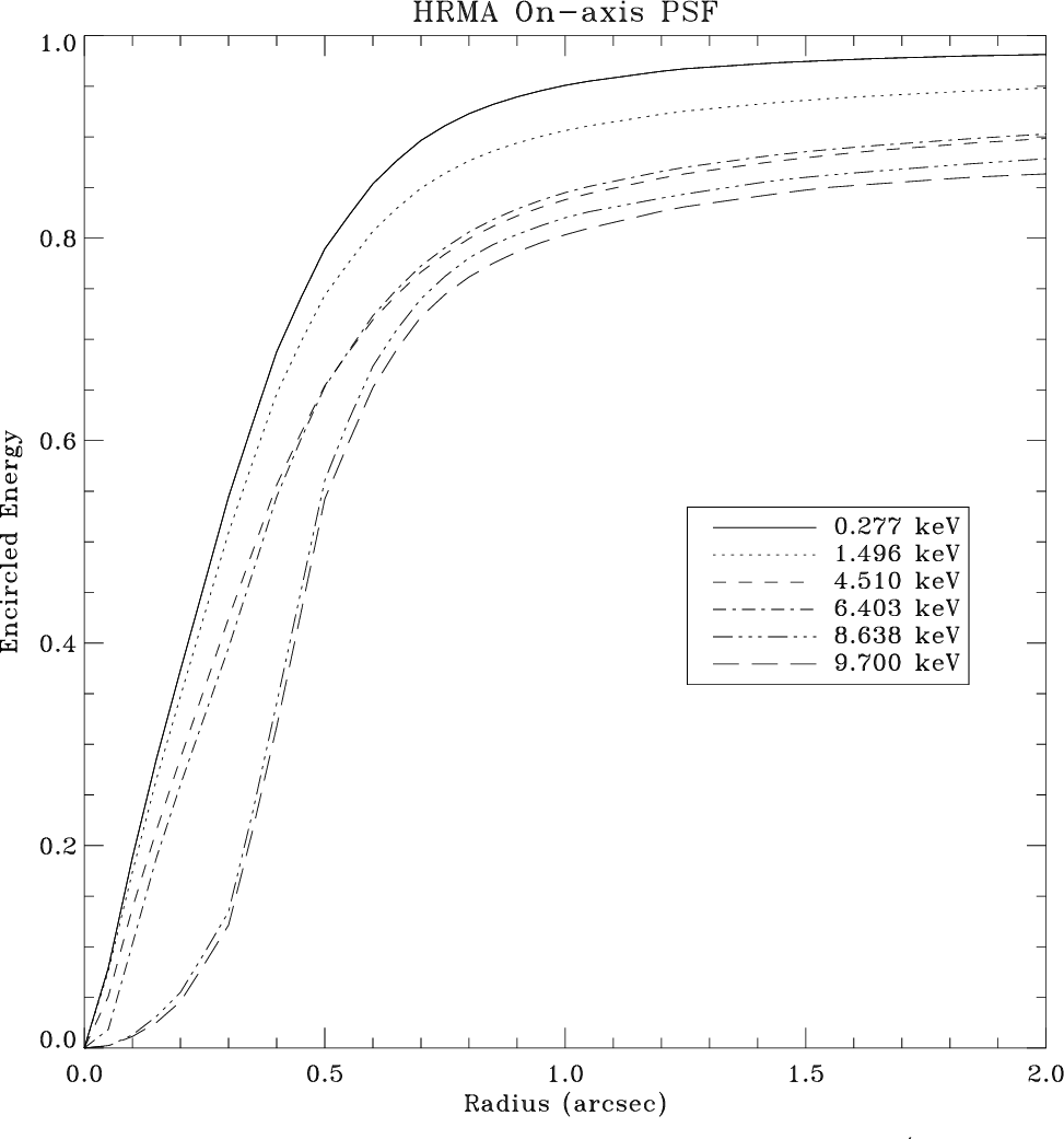

| X-ray: | Encircled Energy Fraction | ||
| E | λ | Diameter | |
| keV | Å | 1 arcsec | 10 arcsec |
| 0.1085 | 114.2712 | 0.7954 | 0.9979 |
| 0.1833 | 67.6401 | 0.7937 | 0.9955 |
| 0.2770 | 44.7597 | 0.7906 | 0.9929 |
| 0.5230 | 23.7064 | 0.7817 | 0.9871 |
| 0.9297 | 13.3359 | 0.7650 | 0.9780 |
| 1.4967 | 8.2838 | 0.7436 | 0.9739 |
| 2.0424 | 6.0706 | 0.7261 | 0.9674 |
| 2.9843 | 4.1545 | 0.6960 | 0.9560 |
| 3.4440 | 3.6000 | 0.6808 | 0.9479 |
| 4.5108 | 2.7486 | 0.6510 | 0.9319 |
| 5.4147 | 2.2898 | 0.6426 | 0.9300 |
| 6.4038 | 1.9361 | 0.6365 | 0.9344 |
| 8.0478 | 1.5406 | 0.5457 | 0.9185 |
| 8.6389 | 1.4352 | 0.5256 | 0.9151 |
| 10.0000 | 1.2398 | 0.4971 | 0.8954 |

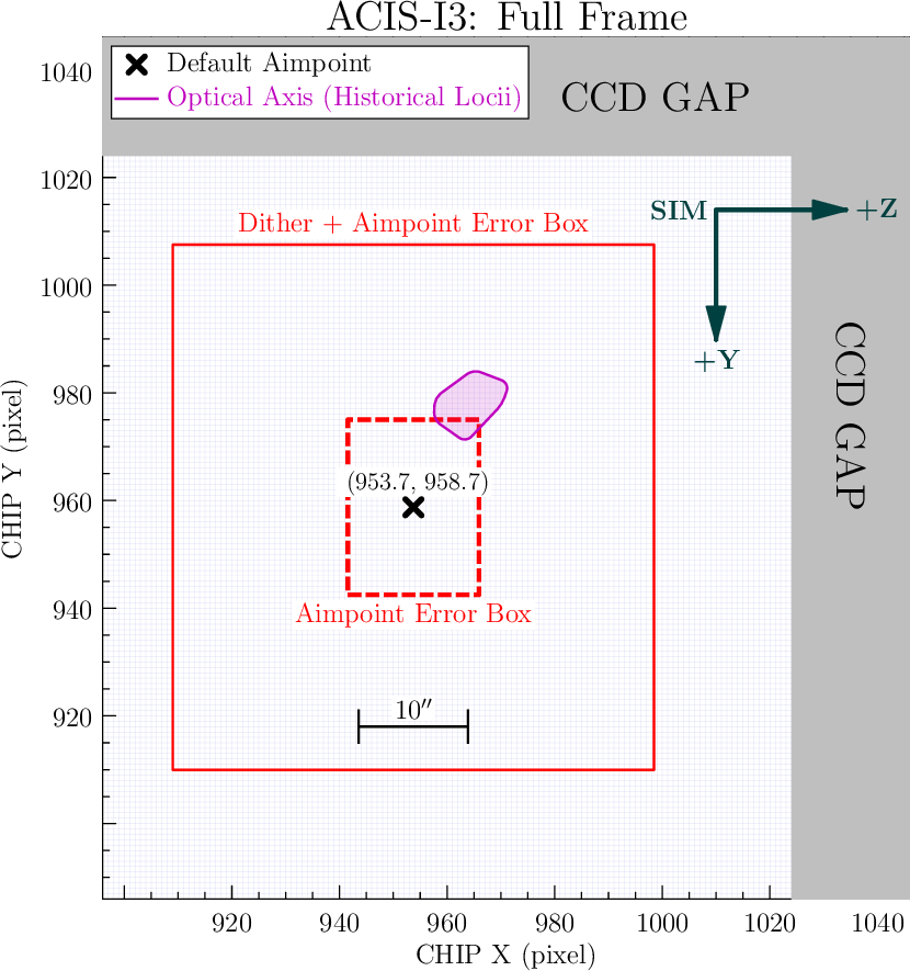
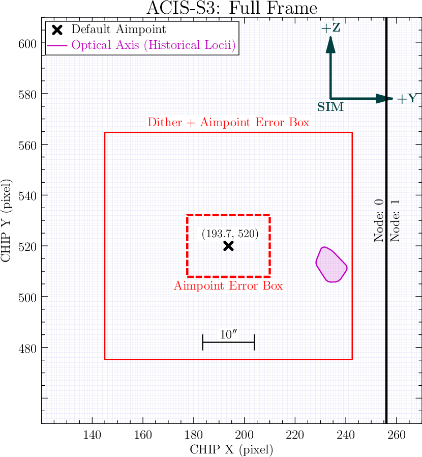
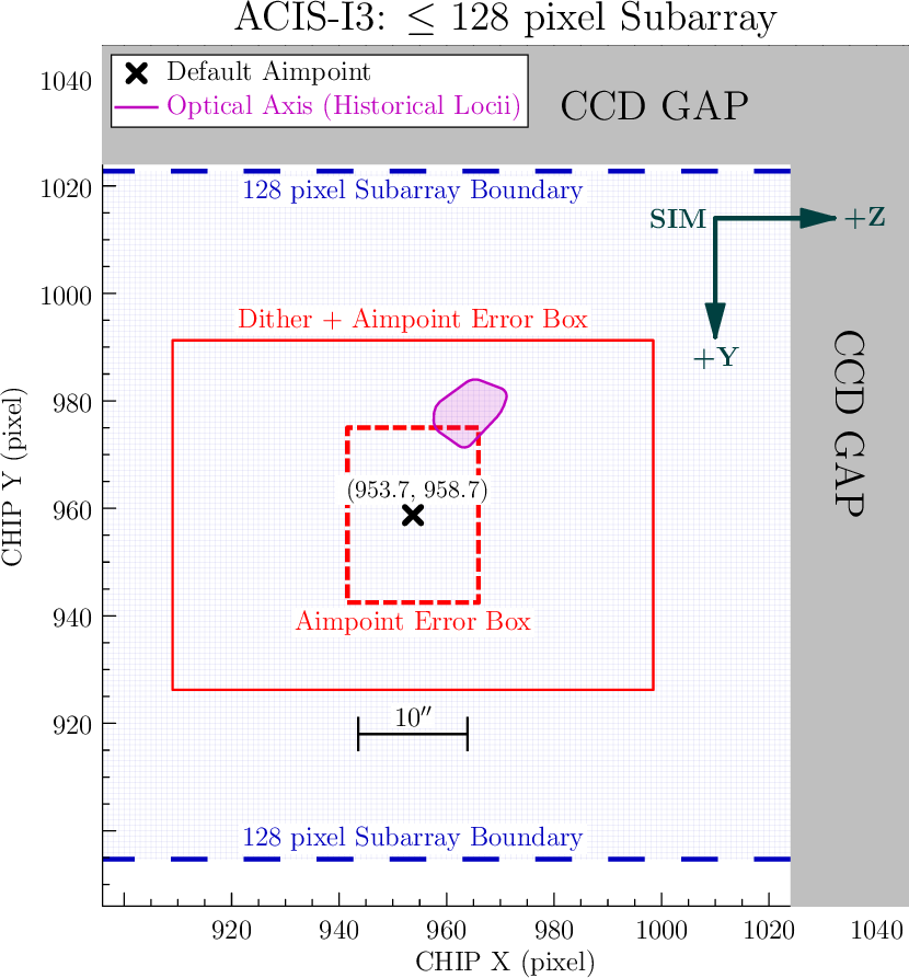
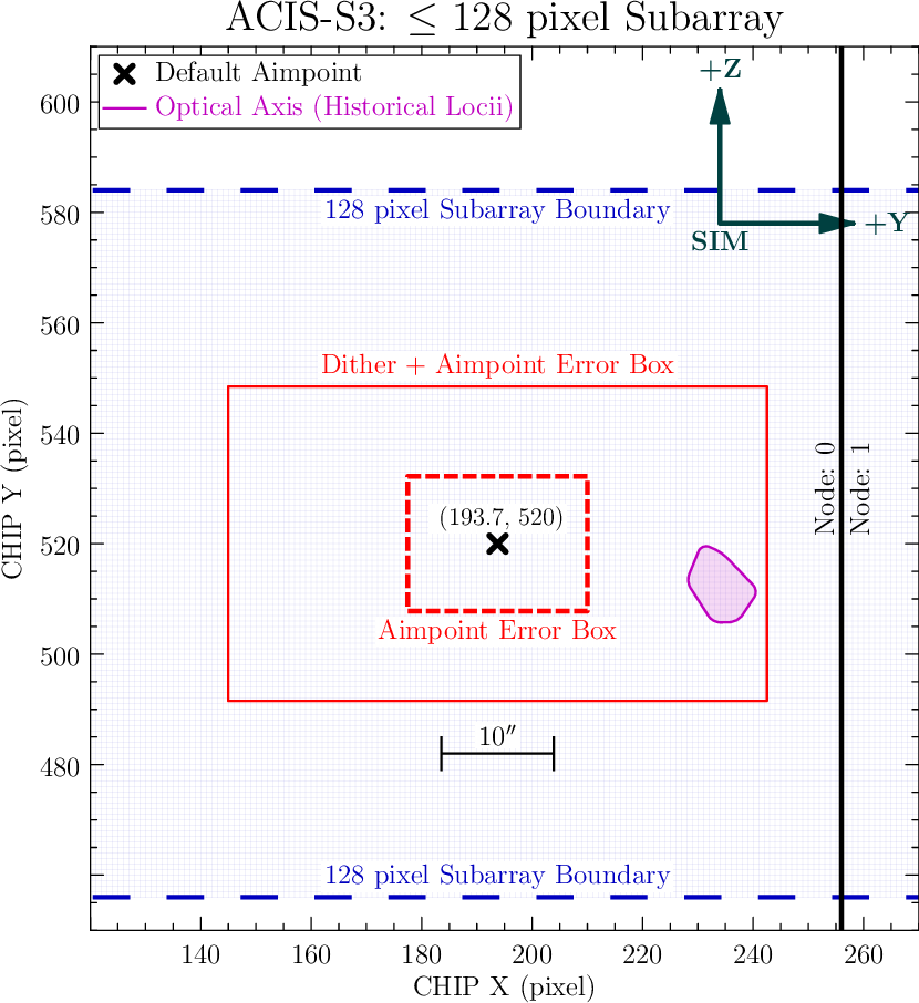
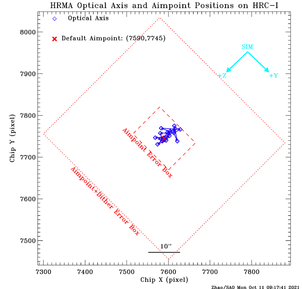
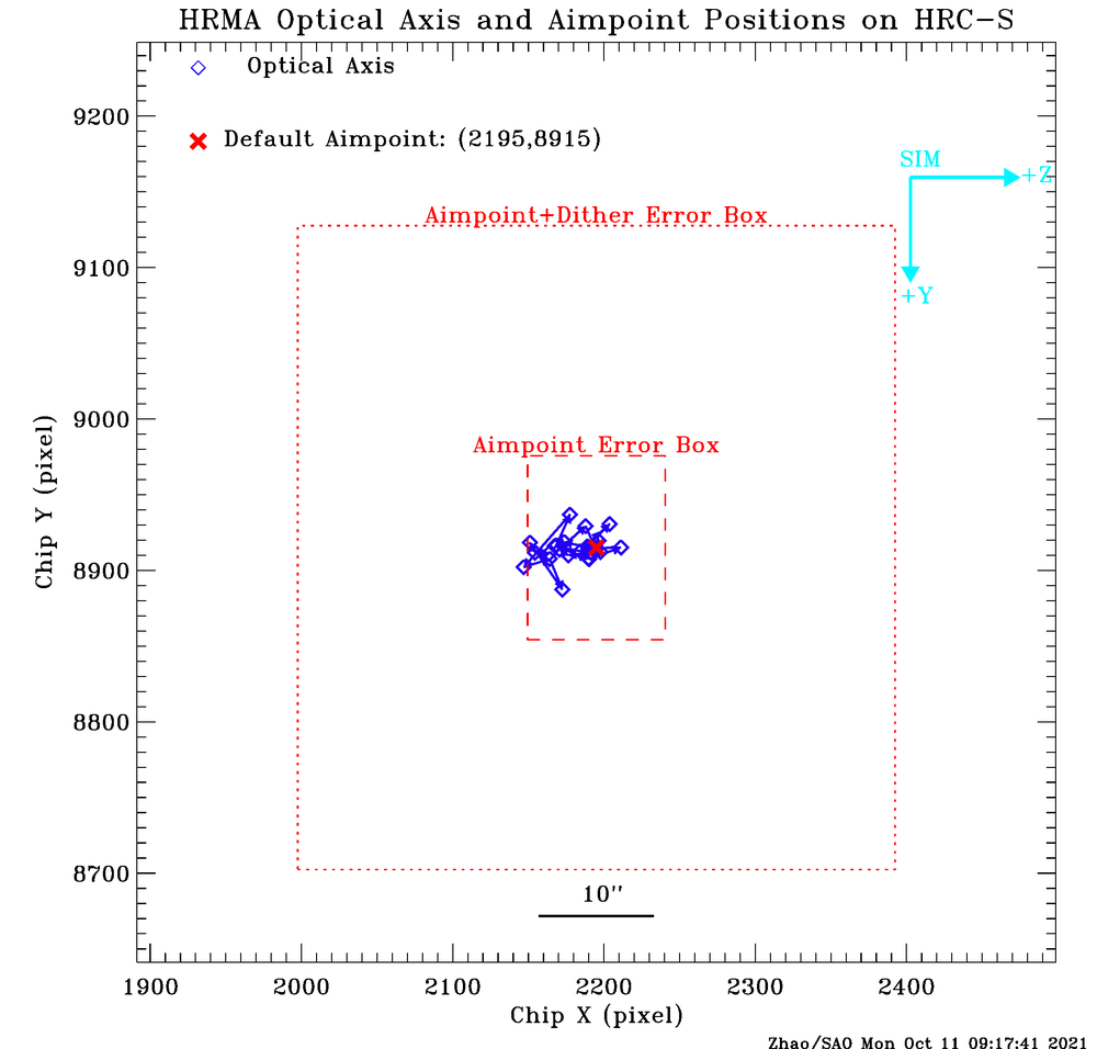
4.5.4 Permanent Default Aimpoints (PDA)The target acquisition is achieved by first pointing Chandra's optical telescope (ACA) to a coordinate based on the telescope roll angle and with a known offset from the target position. Since this offset is fixed, the X-ray telescope (HRMA) should then be pointing to the target. However, because of the thermal changes in the alignment between the HRMA and the ACA, the Chandra effective aimpoint has been drifting slowly around the SIM[-Y,-Z] direction by a few arcsec each year since launch. Before Cycle 18, this drift was mitigated by setting default aimpoints on ACIS-I and ACIS-S using yearly updated point offsets. Starting with Cycle 18 observations, a permanent default aimpoint (PDA) is chosen for each detector. These PDAs are close enough to the optical axis so the PSFs are as sharp as on the optical axis while also far from the chip edges or node boundaries. A predictive thermal model of the alignment between the ACA reference frame and HRMA is used in the planning process to compensate the pointing. However, due to residual uncertainties in this model, error boxes are given around each PDA, indicating the current pointing uncertainty. The dynamical aimpoint adjustment started on 2016-Aug-29. This process has improved the effective aimpoint stability. The error box sizes are based on the observations taken on all the detectors during the 6 month period prior to 2021-Oct. The peak to peak swings of the short term fluctuations are 16 arcsec in the SIM +Y direction and 12 arcsec in the SIM +Z direction. Observers also have the option to request the Y-offset, Z-offset and SIM-Z offset to put their targets at different locations on the detector. These offsets will be calculated from the PDA. Observers can use ObsVis to visualize the target location on the detectors with their chosen offsets. However, the error boxes will be the same size around their chosen location.
4.5.5 Optical Axis and PDA positionsThe current optical axis and PDA locations are listed in Table 4.3. These numbers are used in CIAO and ObsVis. On-axis targets will be imaged near the PDA and inside the error box on each detector. Observers should use this table to check their target location and may request different pointing offset based on their sources to maximize the scientific return. If the observer does not request a specific pointing offset, their target will be put near the PDA. Telescope dither is used to reduce pileup and protect detectors from damage from bright sources. The dither pattern used for the ACIS detectors has been enlarged in Cycle 24 to improve background analysis for the PCAD system (the HRC dither pattern extent is already sufficient). When planning an observation, it is important to take into account the pointing uncertainty in addition to the dither extent to ensure that targets are located appropriately with respect to chip edges and ACIS node boundaries. Table 4.4 provides dimensions for the dither boxes (which include aimpoint error). Note that the dither patterns (and thus the dither boxes) differ for sub-arrays ≤ 128 pixels in order to ensure that dither in the short direction of the sub-array does not move targets out of the active region of the detector. Figures 4.27 - 4.32 show the optical axis and PDA with their error boxes on all four detectors.
4.6 ReferencesAschenbach, B. 1985, Rep. Prog. Phys. 48, 579Aschenbach, B. 1991, Rev. Mod. Astron. 4, 173 Boese, F.G. 2000, Astron. Ap. Suppl. 507, 141 Edgar, R.J., et al. 1997, SPIE Proceedings, 3113, 124 Elsner, R.F., et al. 1998, SPIE Proceedings, 3444, 177 Gaetz, T.J., et al. 1997, SPIE Proceedings, 3113, 77 Gaetz, T.J., et al. 2000, SPIE Proceedings, 4012, 41 Gaetz, T.J., 2004, https://cxc.cfa.harvard.edu/cal/Hrma/rsrc/Publish/Optics/PSFWings/wing_analysis_rev1b.pdf Gaetz, T.J. and Jerius, D. 2005,https://cxc.harvard.edu/cal/Hrma/UsersGuide.html Gaetz, T.J., et al. 2004, SPIE Proceedings, 5165, 411 Giacconi, R., et al. 1979, ApJ, 230, 540 Graessle, D.E., et al. 1998, SPIE Proceedings, 3444, 140 Graessle, D.E., et al. 2004, SPIE Proceedings, 5165, 469 Henke, B.L., et al. 1993, Atomic Data and Nuclear Data Tables, 54, 181 Hughes, J.P., et al. 1993, SPIE Proceedings, 1742, 152 Jerius, D., et al. 2000, SPIE Proceedings, 4012, 17 Jerius, D., et al. 2004, SPIE Proceedings, 5165, 402 Jerius, D., et al. 2004, SPIE Proceedings, 5165, 433 Juda, M., & Karovska, M., 2010 AAS/HEAD Poster "Chandra's Ultimate Angular Resolution: Studies of the HRC-I Point Spread Function", https://hea-www.harvard.edu/~juda/memos/HEAD2010/HEAD2010_poster.html Kashyap, V., 2010 CXC memorandum, "Analysis of Chandra PSF feature using ACIS data", https://cxc.harvard.edu/cal/Hrc/PSF/acis_psf_2010oct.html Kolodziejczak, J.J., et al. 1997, SPIE Proceedings, 3113, 65 Marshall, H.L., 2005 "Improving the Relative Accuracy of the HETGS Effective Area", https://space.mit.edu/ASC/calib/heg_meg/meg_heg_report.pdf Marshall, H.L., 2005a, private communications O'Dell, S.L. and Weisskopf, M.C. 1998, SPIE Proceedings, 3444, 2 Olds, C.R. and Reese, R.P. 1998, SPIE Proceedings, 3356, 910 Schwartz, D.A., et al. 2000, SPIE Proceedings, 4012, 28 Trümper, J., 1983, Adv. Space Res. 2(4), 241. Van Speybroeck, L.P., et al. 1997, SPIE Proceedings, 3113, 89 Weisskopf, M.C. and O'Dell, S.L. 1997, SPIE Proceedings, 3113, 2 Weisskopf, M.C., et al. 2000, SPIE Proceedings, 4012, 2 Zhao, P., et al. 1993, SPIE Proceedings, 1742, 26 Zhao, P., et al. 1993, SPIE Proceedings, 1742, 75 Zhao, P., et al. 1994, SPIE Proceedings, 2011, 59 Zhao, P. and Van Speybroeck, L.P. 1995, SPIE Proceedings, 2515, 391 Zhao, P., et al. 1997, SPIE Proceedings, 3113, 106 Zhao, P., et al. 1998, SPIE Proceedings, 3444, 234 Zhao, P. and Van Speybroeck, L.P. 2003, SPIE Proceedings, 4851, 124 Zhao, P., et al. 2004, SPIE Proceedings, 5165, 482 Zhao, P., 2004, Chandra Calibration Workshop, Cambridge, MA "Chandra Telescope Optical Axis" https://cxc.cfa.harvard.edu/ccw/proceedings/04_proc/presentations/zhao Zhao, P., 2005, Chandra Calibration Workshop, Cambridge, MA "Chandra Telescope Optical Axis and Aimpoint" https://cxc.cfa.harvard.edu/ccw/proceedings/05_proc/presentations/zhao Zhao, P., 2006, CXC Memorandum "Chandra Telescope Optical Axis and Aimpoint" https://cxc.harvard.edu/cal/Hrma/rsrc/Publish/Optics/OpticalAxisAndAimpoint/opt_axis_memo.pdf Zhao, P., 2007, Chandra Calibration Workshop, Huntsville AL "Chandra Telescope Optical Axis and Aimpoint" https://cxc.cfa.harvard.edu/ccr/proceedings/07_proc/presentations/zhao Zhao, P., 2009, Chandra Calibration Review, Boston, MA "The Quality and Stability of Chandra Telescope Pointing and Spatial Resolution" https://cxc.harvard.edu/ccr/proceedings/2009/presentations/zhao Zhao, P., 2011, CXC memorandum "Chandra Aimpoint Drift and Default Offsets" https://cxc.harvard.edu/cal/Hrma/rsrc/Publish/Optics/OpticalAxisAndAimpoint/aimpoint_memo_2011.pdf Zhao, P., 2012, CXC memorandum "Chandra Optical Axis, Aimpoint and Their Drifts" https://cxc.harvard.edu/cal/Hrma/rsrc/Publish/Optics/OpticalAxisAndAimpoint/oxap_memo_2012.pdf Zhao, P., 2013, CXC memorandum "Chandra Optical Axis, Aimpoint and Their Drifts" https://cxc.harvard.edu/cal/Hrma/rsrc/Publish/Optics/OpticalAxisAndAimpoint/oxap_memo_2013.pdf Zhao, P., 2014, CXC memorandum "Chandra Optical Axis, Aimpoint and Their Drifts" https://cxc.harvard.edu/cal/Hrma/rsrc/Publish/Optics/OpticalAxisAndAimpoint/oxap_memo_2014.pdf Zhao, P., 2015, CXC memorandum "Chandra Optical Axis and Aimpoint" https://cxc.harvard.edu/cal/Hrma/rsrc/Publish/Optics/OpticalAxisAndAimpoint/oxap_memo_2015.pdf Zhao, P., 2016, CXC memorandum "Chandra Optical Axis and Aimpoint" https://cxc.harvard.edu/cal/Hrma/rsrc/Publish/Optics/OpticalAxisAndAimpoint/oxap_memo_2016.pdf Zhao, P., 2017, CXC memorandum "Chandra Optical Axis and Aimpoint" https://cxc.harvard.edu/cal/Hrma/rsrc/Publish/Optics/OpticalAxisAndAimpoint/oxap_memo_2017.pdf Zhao, P., 2018, CXC memorandum "Chandra Optical Axis and Aimpoint" https://cxc.harvard.edu/cal/Hrma/rsrc/Publish/Optics/OpticalAxisAndAimpoint/oxap_memo_2018.pdf Zhao, P., 2019, CXC memorandum "Chandra Optical Axis and Aimpoint" https://cxc.harvard.edu/cal/Hrma/rsrc/Publish/Optics/OpticalAxisAndAimpoint/oxap_memo_2019.pdf Zhao, P., 2020, CXC memorandum "Chandra Optical Axis and Aimpoint" https://cxc.harvard.edu/cal/Hrma/rsrc/Publish/Optics/OpticalAxisAndAimpoint/oxap_memo_2020.pdf Zhao, P., 2021, CXC memorandum "Chandra Optical Axis and Aimpoint" https://cxc.harvard.edu/cal/Hrma/rsrc/Publish/Optics/OpticalAxisAndAimpoint/oxap_memo_2021.pdf Portable Document Format (PDF) copies of various aspects of the HRMA calibration can be obtained from the CXC Optics Calibration Group at: https://cxc.harvard.edu/cal/Hrma/XRCFReport.html A detailed guide to using and understanding the HRMA is available at: https://cxc.harvard.edu/cal/Hrma/UsersGuide.html Further information can be obtained from the MSFC Chandra calibration page at: https://wwwastro.msfc.nasa.gov/xray/xraycal/ The current positions of Chandra Optical Axis and Aimpoint, and all the references can be found at: https://cxc.harvard.edu/cal/Hrma/OpticalAxisAndAimpoint.html.
| |||||||||||||||||||||||||||||||||||||||||||||||||||||||||||||||||||||||||||||||||||||||||||||||||||||||||||||||||||||||||