Chandra's Ultimate Angular Resolution: Studies of the HRC-I
Point Spread Function
Michael Juda & Margarita Karovska
(Harvard-Smithsonian CfA)
Abstract
The Chandra High Resolution Camera (HRC) should provide an ideal
imaging match to the High-Resolution Mirror Assembly (HRMA). The
laboratory-measured intrinsic resolution of the HRC is ~20 microns
FWHM. HRC event positions are determined via a centroiding method
rather than by using discrete pixels. This event position
reconstruction method and any non-ideal performance of the detector
electronics can introduce distortions in event locations that, when
combined with spacecraft dither, produce artifacts in source
images. We compare ray-traces of the HRMA response to "on-axis"
observations of AR Lac and Capella as they move through their dither
patterns to images produced from filtered event lists to characterize
the effective intrinsic PSF of the HRC-I. A two-dimensional Gaussian,
which is often used to represent the detector response, is NOT a good
representation of the intrinsic PSF of the HRC-I; the actual PSF has a
sharper peak and additional structure.
Introduction
Chandra's High-Resolution Mirror Assembly (HRMA) is the highest
resolution X-ray optic produced for astronomical observations. The
High Resolution Camera (HRC) was designed to make full use of the HRMA
resolution. Each HRC detector uses a pair of micro-channel plates
(MCPs) to convert the incoming X-ray to charge. The front MCP channel
diameter and pitch determines ultimate possible resolution of the HRC
(HRC-I diameter/pitch = 10/12.5 um, HRC-S = 12.5/15 um). Subsequent
processing by 2nd MCP and read-out are likely to add blur. The
charge-cloud from back of the MCPs is "imaged" on crossed-grid of
wires. X-ray event positions are calculated using the centroid of the
charge on the wire grid. The charge-cloud centroid is determined per
axis with a "three-tap" algorithm. The pixel size for positions is
arbitrary; the default value for standard processing is ~6.43 um or
0.1318 arcsec, which over-samples the PSF. Laboratory measurements of
the spatial resolution on a "flight-like" system had FWHM of 20-25
um.
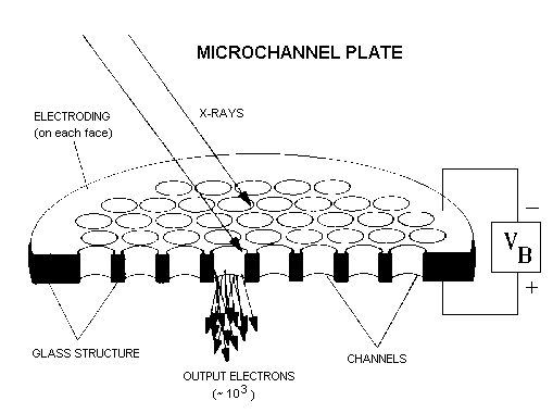 | 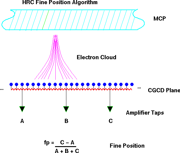 |
| Figure 1: HRC principle of operation: Incoming X-ray interacts with
wall of channel releasing (at most) a few electrons into the
channel. Applied HV accelerates electrons, which impact the channel
wall releasing more electrons, amplifying the signal. The charge cloud
exiting the MCP is collected on a grid of wires. The charge on a wire
is resistively divided between charge amplifiers. The event location
is determined by a centroid of the amplifier signals. |
Performance Details
There are a few issues with the implementation of the charge-cloud
readout (both expected and unexpected) that compromise the
determination of the X-ray location. "Gaps" are generated in images
formed using the simple centroid since an increasing portion of charge
is lost when approaching mid-point between amplifiers. De-gap
corrections are applied to shift the event positions to close the
gap. Electronic ringing in amplifier strings occurs for a subset of
events. If not corrected, the ringing produces jet-like artifacts. The
affected events can be identified and a partial signal correction made
(1 of 3 signals per axis). The de-gap correction attempts to fix the
impact of any residual distortions from the ringing. Non-matching
gains/offsets in amplifier strings exist that were not observed at
component level. Again, de-gap corrections attempt to fix the induced
distortions.The impact of these issues may differ on each axis and
lead to differing resolutions along the two detector axes.
Standard processing applies best know corrections for event-position
reconstruction and standard filtering rejects events with obviously
bad positions. Due to the amplifier-ringing issue some of the
remaining calculated event positions may be shifted slightly away from
their actual location. In the analysis presented here we have
eliminated the events affected by the ringing by rejecting all events
with an amplifier scale (AMP_SF) setting of 3.
Gaussian Fits
A sherpa thread[1] describes how to use an image from a ChaRT[2]
produced ray-trace as the kernel in a two dimensional fit of image
data. The ChaRT ray-trace does not include any detector
effects. Gaussian approximations to detector effects can be added
using MARX[3] or the CIAO tool psf_project_ray. The sigma of the
Gaussian should be derived from calibration. Using the ray-trace
result without including a contribution from the instrument as a
kernel in fits to on-axis unresolved sources provides an estimate for
added blur from the detector (and aspect) as well as an assessment of
whether a Gaussian is an appropriate model for the detector
contribution. Performing such a fit on an observation of AR Lac taken
in the first months of the mission yields a Gaussian FWHM of 4.69 HRC
pixels (0.618 arcsec) for a sigma of 0.262 arcsec. Unfortunately, the
residuals of the fit suggest that this Gaussian blur to the ray-trace
is a poor representation to the actual instrument response. This might
be expected given the assumptions made in this simple treatment. We
have no reason to expect the HRC intrinsic PSF to be a Gaussian.
Ray-traces
In order to study the intrinsic HRC-I point-spread response we first
generated ray-trace simulations for a set of AR Lac calibration
observations using SAOTrace[4] (the engine behind ChaRT). We modeled
the effect of spacecraft dither by calculating set of observed,
source-rate-weighted, pointing offsets (~2000 offsets per
observation). A ray-trace was generated for each pointing offset. The
output rays from each ray-trace were "spatially quantized" onto a
triangular grid that reflects the MCP channel structure, with all rays
that impact a given channel reassigned to the coordinates of the
channel center. Rays were then given random offsets within the channel
area to mimic the loss of event location information produced by the
charge cascade down the channel and the processing by the second
MCP. The known pointing offset for each ray-trace was used to
"de-dither" the set of ray-traces to a common center. The CIAO tool
psf_project_ray was used to convert the combined ray-traces to an
event list.
The ray-trace events were used as a kernel in 2D-Gaussian fits of the
observed source image. We worked with images rotated to the HRC-I
coordinate frame so that the results do not have to be corrected for
the differing spacecraft roll between observations. The table below
gives the resulting FWHM for observations of AR Lac taken each year to
monitor the HRC performance. The fit ellipticity parameter for most of
the fits was ~0.2 but with no preferred direction. The FWHM values of
these fits are slightly smaller than those using ChaRT ray-traces due
to the randomization within the MCP channel that was included the
ray-traces.
| ObsID | Date | FWHM (pixels) | sigma (arcsec) |
|---|
| 1385 | 1999-10-05 | 4.59 +/- 0.05 | 0.257 +/- 0.003 |
| 996 | 1999-12-09 | 3.80 +/- 0.18 | 0.213 +/- 0.010 |
| 1484 | 2000-12-12 | 3.91 +/- 0.15 | 0.219 +/- 0.008 |
| 2608 | 2002-01-27 | 3.94 +/- 0.15 | 0.221 +/- 0.008 |
| 4294 | 2003-02-22 | 3.90 +/- 0.14 | 0.218 +/- 0.008 |
| 5060 | 2004-09-13 | 3.74 +/- 0.13 | 0.210 +/- 0.007 |
| 5979 | 2005-09-27 | 3.47 +/- 0.08 | 0.194 +/- 0.004 |
| 6519 | 2006-09-20 | 3.55 +/- 0.08 | 0.199 +/- 0.004 |
| 8298 | 2007-09-17 | 3.58 +/- 0.08 | 0.200 +/- 0.004 |
| 9640 | 2008-09-07 | 3.42 +/- 0.34 | 0.191 +/- 0.019 |
| 10578 | 2009-09-24 | 3.23 +/- 0.73 | 0.181 +/- 0.041 |
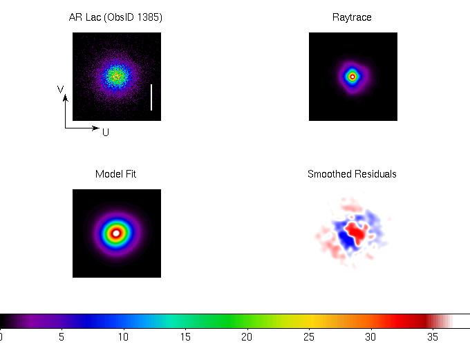
Figure 2 shows the fit results for the first of these
observations. The observed source event distribution is more peaked
than the best-fit Gaussian; this is characteristic of all the fits. A
comparison of the residuals among all the fits showed the same
systematic pattern.
|
|
Figure 2: Results of a 2D-Gaussian fit, using a ray-trace of the
optics as a kernel, to a HRC-I on-axis observation of a point source
(ObsID 1385). The source image and ray-trace were binned in the HRC-I
detector coordinate frame at 0.2 times the nominal pixel size. The
vertical white bar in the source image is 1 arcsec in length. Non-zero
ellipticity was allowed in the fit. The color scale for the smoothed
residuals is red/blue for data greater/less than the model. The
systematic pattern in the smoothed residuals is characteristic of all
fits that we have performed.
|
Deconvolutions
A systematic pattern in the fit residuals suggests that there is
underlying structure in the HRC-I PSF relative to the simple
Gaussian. In order to understand these residuals we have deconvolved
each of the AR Lac observations with the ray-trace simulations. The
resulting images should provide a guide to what we can expect in the
intrinsic structure of the HRC-I PSF.
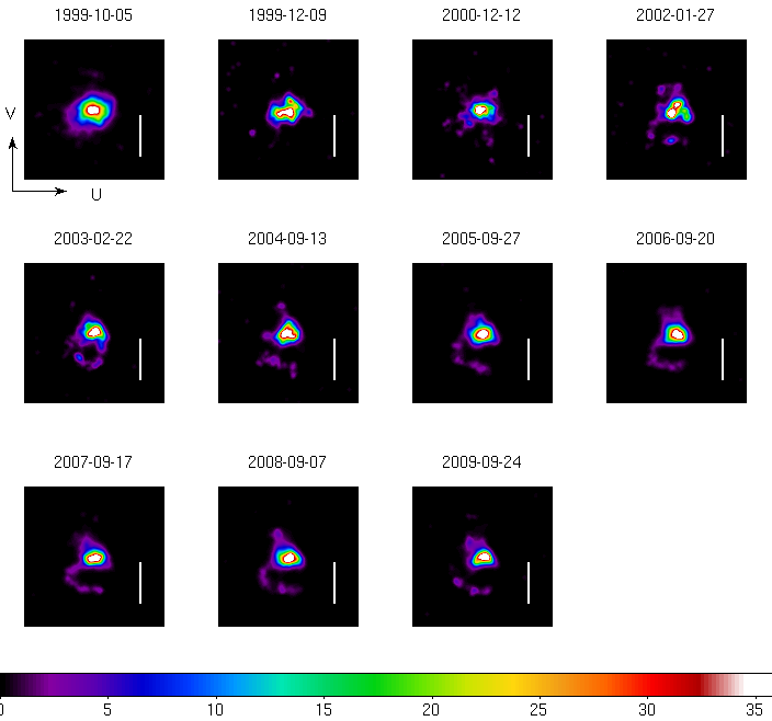
Figure 3 shows the deconvolved images for the AR Lac
observations. This time-sequence of images seems to imply that there
has been evolution in the structure. By the year 2002 observation a
hook-like structure has appeared extending ~0.8 arcsec to the
negative-V side of the main peak. The amount of signal in this hook
region is ~6%. The main peak appears more extended along the U-axis
but also exhibits a triangular shape. The triangular shape may be
related to the MCP channel structure.
|
|
Figure 3: Deconvolution of observed source image with ray-trace image
for the AR Lac calibration observations. The vertical white bar is 1
arcsec in length. By the 2002 observation a hook-shaped extension to
the -V direction has appeared. This feature appears to be stable over
the last several years.
|
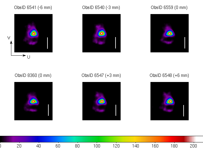
The AR Lac observations were all performed in the same region of the
detector so the obvious question is whether this structure is related
to this position. Figure 4 shows similar images for a series of
observations of Capella in which the HRC-I position was translated
behind the telescope aim-point. The translation was large enough that
distinctly different regions of the detector and charge amplifiers
were used in imaging the source. Structure similar to that in the
later AR Lac observations is present in each of these observations.
|
|
Figure 4: Similar to figure 3 but for Capella calibration observations
that translated the HRC-I behind the telescope aim-point. The offset
position is indicated above each panel. The offsets are large enough
that the dither samples non-overlapping regions of the detector. The
same hook-like feature as seen in the AR Lac data is observed.
|
The Bottom Line
The intrinsic PSF of the HRC-I is not well-represented by a Gaussian;
there is significant underlying structure that is not represented by a
simple function. While we are working to understand the process by
which the HRC hardware or the processing of its signals could produce
this structure, we cannot yet rule out that it is due to un-modeled
performance of the HRMA. An examination of suitable ACIS observations
may resolve this question.
Any observer who sees (or wishes to find) structure in their HRC
observations on arcsec scales should proceed with caution. Applying a
filter to exclude AMP_SF = 3 events can help provide additional
cleaning of the data. Two (or more) observations at differing
spacecraft rolls should help separate image structure due to detector
artifacts from structure in their source.
References
[1] "Accounting for PSF Effects in 2D Image Fitting" http://cxc.harvard.edu/sherpa/threads/2dpsf/
[2] "ChaRT: The Chandra Ray Tracer" C. Carter, et al. ADASS XII ASP Conference Series, Vol. 295, 2003, p.477 http://cxc.harvard.edu/chart/
[3] MARX http://space.mit.edu/cxc/marx/
[4] SAOTrace http://cxcoptics.cfa.harvard.edu/SAOTrace/Index.html
Last modified: Tue May 18 14:35:55 EDT 2010
Dr. Michael Juda
Harvard-Smithsonian Center for Astrophysics
60 Garden Street, Mail Stop 70
Cambridge, MA 02138, USA
Ph.: (617) 495-7062
Fax: (617) 495-7356
E-mail: mjuda@cfa.harvard.edu


